This article provides a high-level overview of how to navigate BIM360 in Estimator.
IMPORTANT: Before you can access your models in Estimator, you will first need to complete the steps in the article How to Set Up BIM360 Docs in Estimator.
If your model is not showing the right properties, you may need to update the Whitelist.
1,. How to access BIM360
2. How to Map takeoff in BIM360
3. How to Compare Models in BIM360
4. How to map line items in Estimator to a takeoff Property in BIM360.
Here is the information on to use each tool in the video - How to use the viewer tools in BIM360
Within the Viewer, a host of options and tools are available that allow you to view and examine a design in detail. The options and tools depend on the type of file you open. Not all tools are available for all files. For example, the Walkthrough option is only available for 3D files.
In general, after you select a tool, you can still continue to use other tools. For example, after you start a walkthrough, you can zoom in and orbit. You can also use the Markup and Comment tools to take a snapshot of a specific view of a model. You may also want to select a part and rotate it or zoom in on it before you add markup comments. To restore your model to the default view, click Home on the top right.
The tables below give information on using each of the tools along the bottom of the Viewer.
Viewing Tools
| Tool | How to use | Tips |
|---|---|---|
|
Walkthrough  |
Ctrl+ Alt+ LMB (left mouse button) over the model to walkthrough. Select > click over model to start walkthrough. Click > drag LMB to change the viewpoint of the model while doing a walkthrough. Click home to end walkthrough and return to the default view for the model. |
Use Ctrl+Alt and click to have more control over the walkthrough.
|
Pan |
LMB (left mouse button) + drag to move design to a different part of the Viewer | |
Zoom |
Click over a part of the design and double-click to zoom. Click over a part of the design and on the keyboard: Ctrl + down arrow to zoom in, Ctrl + up arrow to zoom out. Click over a part of the design and on the mouse scroll wheel (forward/away from user == zoom out, backwards/towards the user == zoom in). Click Home to go back to the default view. |
You can use the Zoom option after selecting other options like Walkthrough, First Person, or Measure.
You may also want to use the Zoom option before you use options like Measure. |
First Person |
Use the First Person tool when you want to navigate through a model as if you were actually inside the model.
Use the directional keys on the keyboard to navigate through your model.
You may also use the WASD and QE keys to move. Use Shift + directional keys to move faster. To adjust walk speed, use the +/- keys. Use the G key to toggle view orientation drag mode. |
When you use the directional keys with the Walkthrough option, it changes your view of the model. Think of it as moving your eyes in a certain direction. With the First Person tool, the person viewing the model is moving in a certain direction.
After you start a walkthrough, you can use the First Person option to navigate through a model. |
Orbit Tools
| Tool | How to use |
|---|---|
|
Orbit  |
LMB (left mouse button) + drag to rotate |
|
Free Orbit  |
LMB (left mouse button) + drag in any direction to rotate and tilt the model as needed |
Camera Options
| Tool | How to use |
|---|---|
Camera Roll |
Alt + Shift + LMB and drag |
Camera Focal Length |
Ctrl + Shift + LMB and drag Ctrl + Shift + scroll wheel Ctrl + Shift + MMB (Middle Mouse button) and drag |
Camera Fit to View |
Position the bounding box center of the current selection at the center of the viewport. The COI will be set at the center of the bounding box as well. The COI is displayed for a second after being set - then fades away. If nothing is selected the model bounding box will be used. |
Reviewing Tools
The Markup and Comment Utilities within the Viewer include the following tools:- Markup
- Comment on Point
- Comment on Object
- Snapshot
- Show/Hide Markers
Examining Tools
| Tool | How to use | Tips |
|---|---|---|
Measure |
Select the Measure option. Click where you want to measure from. Click again at the point that you want to measure to. The measurement is displayed in the Measure pane.
In 2D designs, you can measure the following:
3D measure is enabled for Fusion files. You can measure:
In addition, you can isolate the measured part. Click Settings within the Measure pane and select Isolate Measurement. The rest of the Design will be grayed out. To change unit of measurement, click Settings in the Measure pane and select a unit of measurement from the Unit Type drop-down menu. You can also set precision to 5 decimal places. 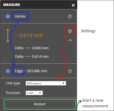 |
Zoom in if needed before you measure.
To measure a new part, click anywhere else within the viewer to release the previous selection or click Restart. The following units of measurement are available:
If your Fusion file is older than October 2015, update it to the latest version to use the Measure feature. |
Explode Model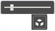 |
Select to take apart a design and see the parts that make up the model. Drag the slider forward to separate the parts. Drag the slider back to bring the model back together. |
After you explode a model, you can rotate it and zoom it to take a closer look at a part. |
Properties |
Click to view properties of a selected part within your design. | Use the Model Browser or the tools on the top left to select a part and click Properties. |
Sectioning Tools
Add box  |
On the viewer toolbar, click Section Analysis the type of sectioning you want to use.
Drag the desired manipulators until the model is sectioned the way you want it. Optional: Add a comment to store the sectioned view with the comment. When done, click Section Analysis again to turn off sectioning. |
Add Z |
|
Add Y |
|
Add X |
Viewer Settings
| Tool | How to use | Tips |
|---|---|---|
Settings |
Go to Customizing Viewer Settings to learn more about this topic. | |
Full Screen |
Click to change Viewer to full screen view and click Allow. Press Esc or click the Full Screen toggle option to exit Full Screen view. |